Genesis Utah Processing
The Genesis spacecraft, launched in August 2001 to collect samples of the solar wind, returned to Earth on 8 September 2004. The Sample Return Capsule (SRC) failed to deploy its drogue parachute and parafoil and subsequently impacted the Utah Test and Training Range (UTTR) at an estimated 310 kph (193 mph).
The goal of the Genesis mission to collect and return samples of the solar wind for precise elemental and isotopic analysis provides the scientific community with a unique set of materials to aid in understanding the origin of our solar system. The spacecraft orbited the Earth-Sun L1 point for 29 months exposing a suite of fifteen types of ultrapure, ultraclean materials in several different locations. Most of the materials were mounted on fixed or deployable wafer panels called "collector arrays". A few materials were mounted as targets in the focal spot of an electrostatic mirror (the “concentrator”). Other materials were strategically placed to maximize the area for solar-wind collection.
- Recovery Processing
- Canister De-integration
- Concentrator Target Removal
- Array Wafer Removal
- Documentation and Packaging
- References
Recovery Processing:
Figure 1: The condition of the science canister after it was retrieved from the field and brought to the high-bay at UTTR.

Recovery Processing: The major portion of the science canister arrived at the prepared high-bay at 2004.09.08.23:45 UTC (all times given will be Universal Coordinated Time in the form of yyyy.mm.dd.hh:mm), approximately 8 hours after impact. Material used to wrap the science canister in the field was opened at 2004.09.09.01:04 UTC to assess the condition and plan the next steps. The science canister was moved into the cleanroom at 2004.09.09.01:34 UTC. It was readily apparent that the science canister could not be transported to NASA Johnson Space Center (JSC) without significant risk of further damage to the sample collectors (Figure 1) due to the structural damage of the canister and the presence of loose fragments. As a result, the decision was made to de-integrate the canister in the cleanroom at UTTR. The sample collectors and wafer fragments would need to be removed from the canister, documented, and packaged individually for transport to JSC. JPL engineers, JSC curatorial personnel, and Genesis Science Team members worked together over a four week period to safely recover the sample collectors from the damaged science canister. The conditions and handling of all hardware and sample collectors were documented (photos, video, and notes as appropriate) to aid in future scientific study of the samples and space-exposed hardware.
Canister De-integration:
Figure 1 in the Recovery Process tab shows a picture of the base of the science canister sheared completely from the side walls. The decision to turn the canister upside down in order to contain as many collector fragments as possible in the nearly intact lid was a critically important decision made in the field and provided a stable base for further de-integration [2].
Figure 2: Gold foil collector
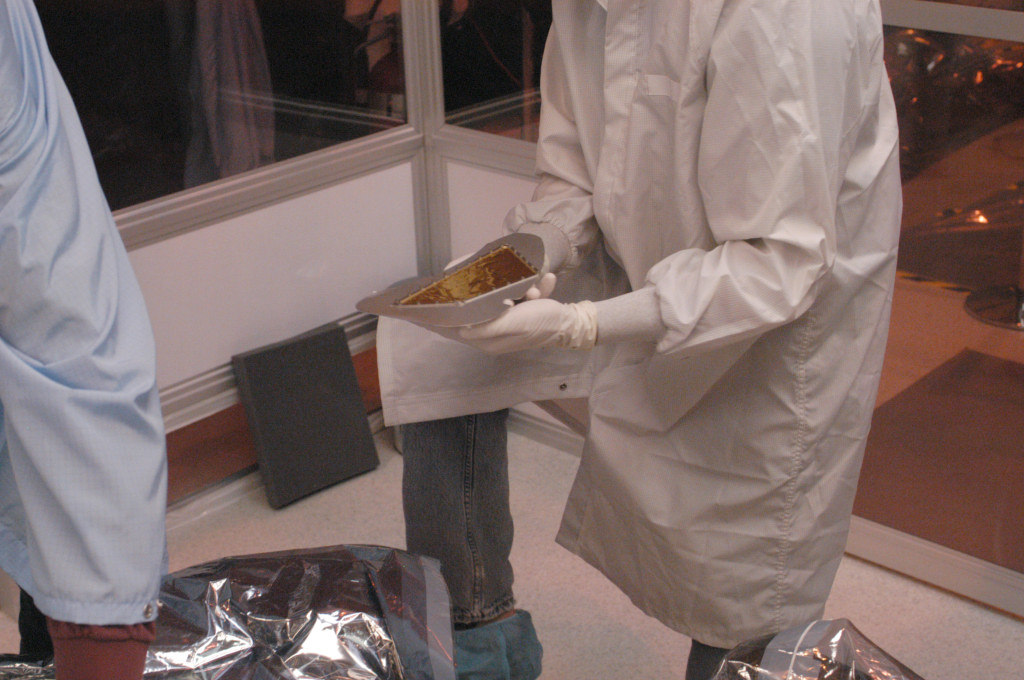
After a thorough inspection it was decided that removal of the concentrator would be our first major objective so that the concentrator targets (which are the highest priority collectors) could be documented and safely packaged. The sidewall and lock-ring of the canister bottom was removed for access to the concentrator. Removing the concentrator provided access to the gold foil collector mounted on the canister thermal closeout panel. The gold foil collector was intact and in good condition (Figure 2).
Due to the compression stress on the thermal panel frame near the array deployment mechanism (ADM) and the close proximity of the thermal closeout panel to the collector array stack it was decided to remove the gold foil collector (the second highest priority collector) from the panel (upside down) instead of removing the thermal panel with the collector attached to minimize the risk of damage to the gold foil. The removal of the thermal closeout panel also resulted in the removal of the polished aluminum collector.
Figure 3: Concentrator target after removal.
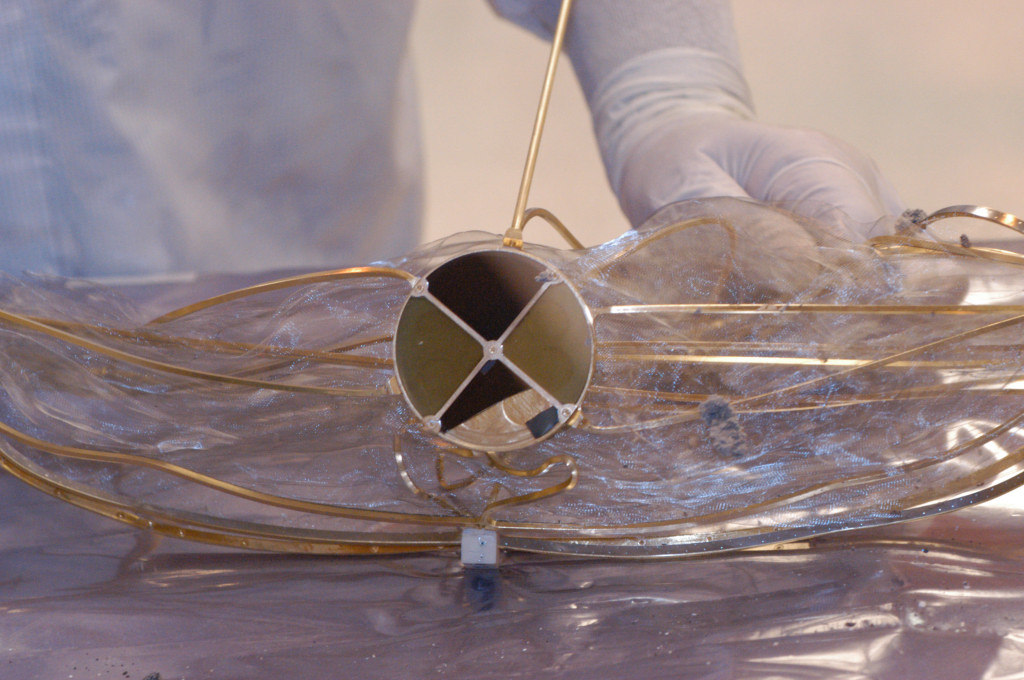
Concentrator Target Removal
With the concentrator separate from the canister, the target was easily visible and fully documented prior to developing the removal procedure. The concentrator targets were mounted on a holder attached to the hydrogen rejection and ion acceleration grids (Figure 3). The gold covered stainless steel support ribs could not be cut without possible damage to the target materials. The concentrator targets were recovered nearly intact and with little visible contamination beyond fine dust. The only fragmented material was the diamond on silicon quadrant, of which more than 85% was recovered in four large fragments, ranging from ~5mm x 5mm to one half of the quadrant. A cover was installed to protect the target and the assembly was secured in an aluminum case for transport.
Array Wafer Removal
Figure 4: Array stack positioned for removal of wafers attached to the face.
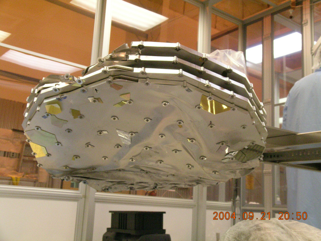
The individual deployable array frames were mechanically crumpled together from the impact requiring that the stack be removed as a single piece. The bulk metallic glass collector (BMG) was mounted on the top of the array deployment mechanism and was removed intact in remarkably good condition. Although the array wafers were the most seriously damaged of the collectors, breaking to greater or lesser extent based on position and material (specifically crystal lattice orientation) there were collectors still attached to the front surface of the array frames (Figure 4). Documenting and removing these wafers from face of arrays was of prime importance. One complete hexagon and three half hexagons were removed intact and many smaller pieces were also removed from the array face allowing unambiguous identification of the collectors. A majority of the collector fragments came loose from the array fasteners and although some fragments became lodged in the array frame isogrid of the neighboring array significant fragment mixing between arrays occurred.
Wafer Fragment Documentation and Packaging
Figure 5: Wafer fragment with scale and color bars as well as the inventory tracking number and container.
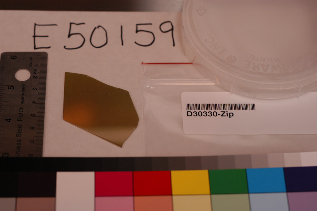
The primary objectives of collector processing in Utah were to document the fragments for material, size, condition / contamination, and location (as possible) and to package the fragments for safe transport with specific emphasis on surface preservation. The documentation primarily consisted of a two-step process due to the desire to de-integrate the canister as quickly as reasonable. As groups of loose fragments were removed from the canister the removal location was documented and the fragments were handed off to another processor for individual fragment identification, photodocumentation, and condition assessment could be done prior to packaging. Simple documentation forms were developed and used to provide consist information for all fragments. The documentation included noting the longest dimension as well as photographing the fragment with a scale and color bar so that true size and true color could be recorded. The size and conditions of the fragments varied considerably [3] necessitating a variety of packaging techniques. Those fragments that were either large or of very good condition were packaged in fluoroware containers when possible (Figure 5).
Figure 6: Stabilizing shards by backside light track adhesion.
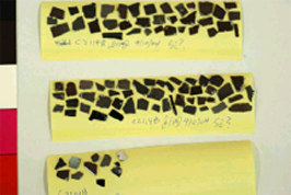
Due to the limited size choices we also packaged fragments in polycarbonate vials and 96-well tissue-culture polystyrene plates with cleanroom wipes used as dunnage and some fragments too small to safely transport in other containers were mounted on cleanroom post-it notes (Figure 6). At special request some fragments were wrapped in aluminum foil prior to packaging. A large number of very small fragments were packaged together in small jars with clean-room wipe dunnage. Packaged fragments were put into pre-numbered ziplock bags for inventory and tracking. Transport to JSC: All collector materials and science canister hardware were loaded onto the NASA #950NA aircraft for transport to JSC at about 2004.10.04.19:00 UTC. The aircraft landed at Ellington Field at approximately 2004.10.04.22:30. The material was escorted to JSC that evening, unloaded and placed in the space-exposed hardware laboratory. Sample containers were moved into the Genesis laboratory on 2004.11.04 where highest value and highest risk materials were put under clean, dry nitrogen.
References
[1] Jurewicz A. J. et al. (2002) Spa. Sci. Rev., 105, 535-560.
[2] McNamara K. M. (2005) Lunar and Planetary Science Conference XXXVI, (2005)
[3] Allton, J. H. et al. (2005) Lunar and Planetary Science Conference XXXVI, (2005)